


服务电话
400-600-5039

精微高博公众号
北京精微高博仪器有限公司
Sales@jwgb.net
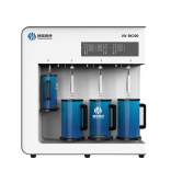
 比表面积分析仪
介孔孔径分析仪微孔孔径分析仪化学吸附仪反应评价装置蒸汽吸附仪穿透曲线分析仪真密度仪压汞仪高压吸附仪热分析仪脱气机质谱仪相关配件
比表面积分析仪
介孔孔径分析仪微孔孔径分析仪化学吸附仪反应评价装置蒸汽吸附仪穿透曲线分析仪真密度仪压汞仪高压吸附仪热分析仪脱气机质谱仪相关配件 化学吸附仪
蒸汽吸附仪
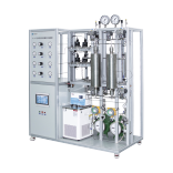
穿透曲线分析仪
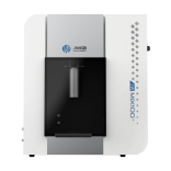
真密度仪
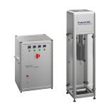
压汞仪
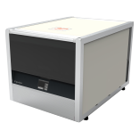
脱气机
质谱仪
化学吸附仪
蒸汽吸附仪
穿透曲线分析仪
真密度仪
压汞仪
脱气机
质谱仪

paper
A B S T R A C T
MgO nanofiber with good morphology was difficult to obtain through high temperature heat-treatment due to the widely existed pulverization phenomenon, which restricted its applications in the high-temperature field. In this work, MgO nanofibers were prepared by electrospinning through mixed precursors: magnesium acetate (MA) and magnesium citrate (MC). The fiber with MC mass content in the range of 30–50% exhibited good hightemperature stability and the original feature was preserved after heat-treated at 1000 °С. A plausible formation mechanism of the polycrystalline MgO nanofibers was provided in the present paper. Suitable confection of MA and MC brought a milder decomposition process and led to a more compact structure of MgO nanofiber, which contributed to the excellent high-temperature stability. The considerable effects of microstructure on thermal
conductivity of the fiber were discussed. The method in this paper has greatly expanded the solution scope for preparing electrospun fibers with expectation of structure modification and strength enhancement.
1. Introduction
Among all kinds of metal oxide materials, magnesium oxide (MgO) in bulk or nanoscale holds a special status as it has wide applications in various fields. MgO in bulk has been extensively applied in industrial circle such as paper industry, paint industry, rubber industry, ceramics, refractory, etc. [1]. Different from the bulk material, nanoscale MgO possesses excellent thermodynamic, optical, electronic and special chemical properties [2,3]. Nanoscale MgO with different morphologies was utilized to catalyze some organic reactions [4–7]. Particularly,
MgO micro-sheets showed strong catalytic activity in Claisen-Schmidt condensation reaction which could produce a well-known anticancer ingredient named as chalcone [8,9]. Nanoscale MgO materials with high specific surface area were “destructive adsorbents” for the extirpation of toxic chemicals [10]. For example, mesoporous MgO nanoscale materials were utilized to remove heavy metal ions [11], toxic dyes [12] and fluoride from water [13], to suppress Cd uptake by crops [14] and applied for acidic gas adsorption [15]. In addition, MgO nanoparticles were also used for air purification as an adsorbent [16].
Antibacterial activities of MgO were investigated that nanoscale MgO could destroy the cytomembrane of bacteria and thus kill them through reacting with the peptide linkages [17,18]. Furthermore, MgO has been used in optoelectronic fields like photoluminescence [19], passivation layer of film capacitor and high electron mobility transistors [20] and additives in high-temperature superconductors [21].
As one-dimensional nanomaterial, MgO nanofiber has advantages in practical applications. MgO fiber is an attractive material for refractory and heat insulation applications due to a high melting point (2850 °C) and a low thermal conductivity [22]. However, MgO nanofiber is likely to have lower thermal conductivity as its ultra-fine diameter. When used as catalyst and adsorbent, MgO nanofibers are more convenient for separation from reaction mixture and easy for recycling than MgO nanoparticles[23]. Besides, MgO nanofibers also performed much better than that of MgO powders when used to immobilize the molten electrolyte in thermal batteries [24].
Among sundry methods to prepare one-dimensional material, electrospinning has received much attention by virtue of its unique advantages: simple apparatus, low cost, numerous spinning material and controlled process. Electrospun MgO nanofibers were fabricated through PVA/magnesium acetate composite as precursor and calcinations at 800 °C by Shao et al. [25]. Submicrometer MgO fibers and tubes were prepared by Hota et al. from electrospun PVP/magnesium acetate composite fibers with heat-treatment at 700 °C [26]. As we know, the performance of nanofibers greatly depended on their structure and morphology, including fiber diameter, length, and microstructure.
However, the self-destruction during heat-treatment impedes the potential application of electrospun MgO fibers. Reducing the brittleness as well as achieving good fiber feature at high temperatures is the http://dx.doi.org/10.1016/j.ceramint.2017.08.199 Received 8 August 2017; Received in revised form 22 August 2017; Accepted 25 August 2017
Corresponding author.E-mail address: xqwang@sdu.edu.cn (X. Wang).
Ceramics International 43 (2017) 16210–16216
Available online 01 September 2017
0272-8842/ © 2017 Elsevier Ltd and Techna Group S.r.l. All rights reserved.
MARK
primary task of fabricating ultrafine MgO fibers.
In the present work, MgO nanofibers were fabricated by a new kind of precursor sol via electrospinning and subsequent heat-treatment. In literature, heat-treatment temperatures of electrospun MgO fibers were just reached 800 °C. While the cotton-like feature successfully preserved after MgO fibers prepared in this work heat-treated at 1000 °C. Thermal behaviors during the decomposition and morphology of obtained fibers were studied. As one of the primary functions of refractories, the
thermal conductivity of MgO fibers was measured to probe into the relationship between which and the microstructure of the fibers. The mechanism responsible for the microstructure of MgO nanofibers was proposed and discussed on the basis of the results obtained in the present paper. The formation mechanism was expected to be applicable for fabrication of various inorganic fibers. And the MgO nanofibers with high-temperature stability and low thermal conductivity had the potential for high-temperature applications and for large scale fabrication.
2. Experimental details
2.1. Materials
Citric acid (C6H8O7·H2O, ≥ 99.5%, Kermel Chemical Reagent Co.,Ltd., Tianjin, China), magnesium oxide (MgO, ≥ 98.5%, Sinopharm Chemical Reagent Co., Ltd., Shanghai, China), magnesium acetate tetrahydrate (MA, Mg(CH3COO)2·4H2O, ≥ 99.0%, Kermel), polyvinylpyrrolidone (PVP, (C6H9NO)n, Shanghai Aladdin Reagent Co., Ltd.,
Shanghai, China, molecular weight 1.3 million), deionized water (resistivity no lower than 18.2cm). All the chemicals were analytical reagent grade and used as received without any further purification.
2.2. Preparation of sols for electrospun
2.2.1. Synthesis of magnesium citrate precursor
Citric acid and MgO were mixed in a beaker with a molar ratio 1:2, then dissolved in deionized water and stirring for 3 h at 50 °C. After cooling to room temperature, the solution was filtered by suction filtration.
The filtered clear solution was concentrated to dry powder with a rotary vacuum evaporator at an evaporation temperature of 70 °C. After the above steps, magnesium citrate (MC) powder was synthesized.
2.2.2. Preparation of mixed precursor sols
MC and MA were mixed in six beakers at various mass ratios listed in Table 1 and marked as S0–S5 respectively. Then PVP (0.50 g) and deionized water (15.00 g) were added into each sample. All the samples were stirred for 5 h at 40 °C to form see-through colloidal solutions, and then ageing for 2 h or more.
2.3. Fabrication of precursor fibers
The precursor fibers were fabricated by electrospinning equipment assembled in laboratory. Electrospinning process was carried out with the voltage of 18 kV at room temperature. Humidity of ambient environment was controlled around 30% by a dehumidifier. The distance between nozzle and collector was 15 cm, and the feeding rate was 0.6 mL/h. After electrospinning, the collected fibers were dried for over
24 h at 50 °C in a drying oven.
2.4. Heat-treatment process
The dried fibers of 6 samples were heat-treated in muffle furnace at the rate of 1 °C/min from room temperature to 600 °C and remained for 1 h at the temperature, and then cooling to room temperature along with the furnace. Besides, fibers of sample S3, S4 and S5 were heattreated by the use of the same furnace at the rate of 1 °C/min from room temperature to 600 °C, 2 °C/min to 800 °C/1000 °C and remained for 1 h at final temperatures.
3. Characterization
The thermal behaviors were studied with a thermogravimetry and differential scanning calorimetry (TG/DSC) simultaneous thermal analyzer (SDT Q600 v8.3 Build 101, TA, US), at a heating rate of 10 °C/min from room temperature to 800 °C in air. Fourier transform infrared (FTIR, ALPHA-T, Bruker, Karlsruhe, Germany) spectrum was measured with a RT-DLATGS spectrometer using the KBr pellet method with a resolution of 4 cm−1 in the region 4000–400 cm−1. The crystalline phases were identified using an X-ray diffraction (XRD, D8 Advance, Bruker, Germany) diffractometer, operated at 40 kV and 40 mA, with Cu-Kα radiation using a graphite monochromator in the range of 10–90° with a step size of 0.04°. The microstructures and surface morphologies of the fibers were observed using scanning electron microscope (SEM,S-4800, Hitach, Japan) at an accelerating voltage of 7 kV. In order to enhance the conductivity of the samples, they were gold coated using ion sputter (E-1045, Hitach, Japan) before taking SEM. The Brunauer-Emmett-Teller (BET) surface area was measured using specific surface area instrument (JW-BK112, JWGB Sci & Tech, China). Diameter distribution of the fiber was measured using a software named Nano Measurer. The fibers heat-treated at 1000 °C were grinded with 5% PVP aqueous solution and infused in a mold to obtain a sheet (4 mm ×4 mm × 1 mm) under a uniaxial press of 8 MPa for 30 s. The sheet was heat-treated at 800 °C to completely remove the PVP and then used for thermal conductivity test. The thermalconductivity was measured by using a NETZSCH LFA457 instrument (LFA457, NETZSCH, Germany), and the value at each point was the average of triplicate analysis with standard derivation less than 0.01 W/(mK). The density and porosity of the pellets were measured by the Archimedes method.
4. Results and discussion
4.1. Thermal behaviors of fiber samples
4.1.1. TG and DSC analyses
The thermal behaviors of the precursor fibers were shown in Fig. 1.It could be noted from Fig. 1(a) that during the whole heat-treatment process there were two major mass loss stages. The first stage was below 300 °C, which could be attributed to the loss of free moisture along with the dehydration of the precursor fibers. The second mass loss stage was between 300 °C and 550 °C, which resulted from the pyrolysis of precursor fibers and volatilization of the pyrolysis products. There was almost no mass loss at higher temperatures, indicating that most of the organics and other volatiles (H2O, COx, etc.) were removed at around 550 °C. In DSC curves (Fig. 1(b)), a shallow endothermic peak was located at around 120 °C, paralleling to the first mass loss stage.
Three obvious exothermic peaks (symbolized as P1, P2 and P3 by the temperature rise order) in DSC curves (Fig. 1(b)) were distributed in three different temperatures, corresponding to the second mass loss stage at around the same temperature range. P1 at about 350 °C was mainly caused by the pyrolysis behavior of MA [27], and it weakened with the addition of MC into precursor mixture. P2 at around 460 °C was rather weak in S1 and S2, but came into sight since S3, which might be attributed to the decomposition of MC and the crystallization of Table 1
Mixtures of MC and MA with different ratios in 6 samples.
Sample Mass ratio (MA:MC) MC mass content (%)
S0 0:10 0
S1 1:9 10
S2 1:4 20
S3 1:2 33.3
S4 2:3 40
S5 1:1 50
MgO. P3 at around 520 °C was generated by the oxidative combustion of the remained organics [28], while it only appeared when the samples (S1–S5) contained MC.
It could be found that DSC curve of S0 only contained P1 and a neighbor peak on an exothermic platform, which was paralleling to the fast mass loss from 310 °C to 450 °C. The other DSC curves (S1–S5) included three peaks P1, P2 and P3 which were distributed in a wider range. At the second mass loss stage, it is obvious that TG curve of S0 was rather steeper than those of S1–S5. In fact, the final crystallization temperatures of S1–S5 were postponed to higher temperatures due to the existence of MC. The wider decomposition temperature range could bring about milder pyrolysis process. Thus it seemed reasonable to conclude that fibers spun from MA/MC precursor sols exhibited milder pyrolysis process compared to those spun from MA precursor sol.
4.1.2. IR spectroscopic analyses
FT-IR spectrum was employed to further study the thermal decomposition behavior of the fiber. The FT-IR spectra of the as-prepared precursor fibers were given in Fig. 2(a). Assignments [29–32] of precursor fibers at room temperature were listed in Table 2. The band at 1294 cm−1 was assigned to –CH2 twisting vibration created by PVP [30]. It could be concluded from the spectrum of S0 that bands at 1349, 1054, 1030, 949, 663 and 623 cm−1 belonged to MA [31]. The peak at 516 cm−1 was ascribed to Mg-O bond in magnesium carboxylates [25].
In the spectra of the other fibers (S1–S5), new bands (weak) located at 1103, 928 cm−1 appeared, which were ascribed to the in-plane and outplane bendings of C-O-Mg for MC [32]. The differences among S0 and the others were small, which might be due to some of the peaks of carboxyl groups in MA and MC were overlapped.
The FT-IR spectra of S0 and S5 heat-treated at different temperatures were exhibited in Fig. 2(b). The FT-IR spectra changing trend of S0 and S5 was no obvious differences. After heat-treated at 300 °C, most bands got weak but still existed, which meant that the main structure of carboxylates and PVP began to disintegrate. While other bands between 1400 cm−1 and 600 cm−1 disappeared in the spectra of the samples heated-treated at 400 °C, corresponding to P1 (350 °C, the pyrolysis of MA) in Fig. 1(b). In addition, a wide band at 500 cm−1 attributed to Mg-O bond formed [25], indicating the formation of crystalline MgO which crystallized from MA. The peak at 865 cm−1 might belong to Fig. 1. TG (a) and DSC curves (b) of six samples (S0–S5). Fig. 2. FT-IR spectra of (a) six precursor samples (S0–S5), (b) precursor samples S0 and S5 before and the samples heat-treated at different temperatures: 300 °C, 400 °C, 500 °C and 600 °C.
Table 2
Assignment for precursor fibers at room temperature.
Wavenumber (cm−1) Assignment
3400 -OH str.
1580 -OH asym.str.
1430 -OH sym.str.
1349 -CH3 def.
1294 -CH2 twist.
1103 C-O-Mg in plane
1054 -CH3 def.
1030 -CH3 rock.
949 C-C str.
928 C-O-Mg out of plane
663, 623 H2O rock
516 Mg–O bond carbon-containing products [31], being exposed while part organics removed. Bands of organics were dismissed at 600 °C, indicating that organics were already removed.
4.1.3. Crystallization process analyses
Fig. 3(a) showed the XRD patterns of S0 and S5 after heat-treated at different temperatures ranging from 300 °C to 600 °C. The XRD pattern of sample S0 indicated the anhydrous magnesium acetate phase in fibers at 300 °C. However, the fibers of S5 were still amorphous at a treatment temperature of 300 °C. After heated at 400 °C, well-defined crystal diffraction peaks appeared at 2θ = 36.8° (111), 42.8° (200), 62.2° (220), 37.2° (311) and 39.2° (222), which were in agreement with JCPDF: 71-1176 and proved the crystallization of cubic MgO. Here the XRD outcomes were consistent with exothermic peaks P1 (350 °C, the pyrolysis of MA) in TG-DSC results. With the increase of the heattreatment temperature, the intensities of MgO peaks increased gradually.
Together with TG-DSC curves and FT-IR spectra, it could suggested that the thermal behaviors of the samples heat-treated between 400 °C and 500 °C mainly included decomposition of organics, volatilization of volatile matters and continuous crystallization of MgO. When the heattreatment temperature was lifted to 600 °C, the crystallinity increased substantially, which was in good agreement with P3 (520 °C, the crystallization of MgO from MC) in DSC curves (Fig. 1(b)). The XRD patterns of fiber samples heat-treated at 600 °C were shown in Fig. 3(b).The distinct and regular peaks proved all the six samples were cubic MgO. What is more, no traceable influences could be detected in various samples with different composition.
4.2. Microstructure and morphology investigation The SEM photographs of fibers after heat-treated at 600 °C were exhibited in Fig. 4. Fig. 4(a1) indicated that MgO particles were assembled as a monolayer, and thus, presented a tubular hollow structure to fibers of S0 (Fig. 4(a2)). Unfortunately, the fibers got broken and serious fracture due to the loose structure. Interestingly, similar hollow pipe structure could also be found in MgO fibers prepared by magnesium acetate (Hota et al.) [26] and magnesium propionate (Zheng Fig. 3. XRD patterns of (a) the samples S0 and S5 heat-treated at different temperatures (300 °C, 400 °C, 500 °C, 600 °C), and (b) six samples heat-treated at 600 °C.
Fig. 4. SEM images of fiber samples (S0–S5) heat-treated at 600 °C. et al.) [31]. Hota et al. supposed that the hollow structure were initially determined during the process of electrospinning that a thin polymer composite skin was formed distinctly on the outer layer of the fiber due to rapid solvent evaporation from the surface [26]. Besides, the mechanism for formation of hollow particles proposed by Koga et al. that the internal water vapor pressure led to formation of hollow particle
might be utilized to account for the hollow structure of the fiber [33].
However, the actual mechanism how this structure formed was still unclear and needed to be explored further. Damaged condition was reduced as structure of S1 (Fig. 4(b)) and S2 (Fig. 4(c)) got more compact. However, their shapes were irregular and the surfaces were unsmooth. Fibers of S3, S4 and S5 showed relatively compact structures with uniform nanoscale particles and smooth surfaces without holes and beads (d1–f2). It was clear that with the appropriate confection of precursor sols by MC and MA, uniform MgO fibers with compact structure and smooth surface could be obtained.
Then the fibers of S3, S4, and S5 were further heat-treated at 800 °C and 1000 °C. All the three samples kept fluffy cotton-like feature after heat-treated at 1000 °C, and no noteworthy rupture phenomenon was found (see Fig. S1 in Supporting information). The SEM photographs of further heat-treated samples were displayed in Fig. 5. It could be seen that MgO fibers were ultra-fine and quite uniform, and, diameter distributions of the fibers were carefully counted (see Fig. S2 in Supporting information and Fig. 6). As seen in Fig. 6, the average diameter of fibers in all the three samples decreased to 235±5 nm at 1000 °C. Seen from magnified images (Fig. 5), one could find that the grains were slightly grown up but they still closely packed at 1000 °C. However, some grains bulged out the surface of S4 and S5 and caused the surface unsmooth more or less after heat-treated at 1000 °C, while the surface of S3 was still relatively smooth without protrusion. It might suggest that there were less gaps or pores existed among grains of S3 than the other two samples as the crystallization process completed. Table 3 showed that the specific surface area of fiber S3 was less than those of S4 and S5, which could be an evidence for that fiber of S3 was more compact. 4.3. Formation process of MgO nanofiber The formation mechanism of MgO nanofibers with different morphologies could be supposed as depicted in Fig. 7. The precursor Fig. 5. SEM images of fiber samples (S3, S4 and S5) heat-treated at 800 °C, 1000 °C. Fig. 6. Average diameters of fibers heat-treated at different temperatures for 1 h.
Table 3
Apparent density and porosity of the fiber sheets at room temperature and surface area of fibers heat-treated at 600 °C, 1000 °C for 1 h.
Fiber sheet Surface area of fiber
Apparent density (g/cm3) Porosity (%) 600 °C 1000 °C
S3 2.38 47.06 96.846 13.489
S4 2.17 46.09 101.199 18.538
S5 2.01 47.86 113.153 19.183
fibers before heat-treatment were amorphous state (a. I and b. I).
Fig. 7(a) showed the structure evolution of fiber fabricated by MA precursor. During the heat-treatment, MgO grains emerged in the fiber when the temperature reached the initial crystallization temperature of MA (a. II). As temperature rose, more MgO grains crystallized in succession and slightly touched each other. However, due to the rapid mass
loss and sharp heat releasing during the thermal decomposition, the MgO grains failed to fill the space where the organic component left (a.III). Therefore, a porous and brittle fiber with grains only gently contacted was obtained (a. IV). As described in the sketch, the fiber appeared an incompact network structure, just as the SEM image of Fig. 4(a2).
The process of structure change of fiber fabricated by MA/MC precursor was portrayed in Fig. 7(b). MgO grains firstly crystallized out from amorphous MA, dispersed and fixed in situ in the amorphous MC (b. II). As MC began to crystallize at a higher temperature, the subsequent formed grains adhered to the pre-existing grains (b. III). At some stage the fiber in Fig. 7(b) exhibited a network structure similar to fiber in Fig. 7(a). Nevertheless, plenty of MgO grains crystallized out continuously as temperature rose and gradually filled the gaps where volatiles left (b. IV). When the crystallization finished, MgO nanofiber with compact grain structure as shown in Fig. 4(f2) were obtained. Based on the above analyses, it is assumed that the removal of pyrolysis intermediates from fiber fabricated by MA/MC precursor proceeds via a more moderate reaction compared to that of fiber fabricated by MA precursor. Besides, the facile heat releasing and slow mass loss rate gave rise to a milder pyrolysis process, which contributed to exhibit compact structure and maintain the self-structure of the fiber.
4.4. Thermal conductivity of MgO nanofibers Apparently in Fig. 8, the thermal conductivities of S3, S4 and S5 decreased in turn in lower temperature range. For fiber sheets, both apparent density and diameter of fiber could significantly affect the thermal conductivity. As mentioned above, the diameters of fibers for three samples were almost the same, so the effect of diameter was not considered. While in Table 3, the apparent density of the sheets decreased from S3 to S5, which corresponded to the performance of thermal conductivity. Furthermore, large porosity and surface area tend to decrease the thermal conductivity [34,35]. Seen from Table 3, one could know that S5 possessed the largest porosity and surface area among the three samples, which was consistent with its lower thermal conductivity. As depicted in Fig. 8, the thermal conductivity of the three samples decreased with increasing temperature to a minimum and then increasing at higher temperatures. The decrease before the minimum largely due to anharmonic phonon scattering, i.e. the Umklapp
phonon-phonon process [36]. For materials with porosity exceeding 30%, heat conduction was significantly diminished relative to thermal radiation and to the conduction through the gas phase [37].
Hence, the increasing thermal conductivity might due to the effect of radiant-heat transfer through the gas phase [38]. One could find that the thermal conductivity of S4 exceeded S3 when the measured temperature was higher than 600 °C (see Fig. 8). That was due to the density of S4 above 600 °C was larger than that of S3 as the different thermal expansion coefficient of the two samples.
5. Conclusion
In the present work, MgO nanofibers were prepared by the use of electrospinning technique. When the mass percent of MC was 30–50% in MA/MC mixture, the fibers heat-treated up to 1000 °C were rather uniform with average diameter of 235±5 nm and kept in shape without pulverization. Compactness of MgO nanofiber varied with the mass ratio change of MA and MC in the precursor. Compared with those of S4 and S5, fibers of S3 were more compact and exhibited better morphology after heat-treated at 1000 °C. However, fibers of S5 showed the largest surface area and lowest thermal conductivity. A probable model based on thermal analyses was proposed to describe the formation process of MgO nanofiber. The mixed precursors extended the crystallization temperature ranges and, thus, gave fibers a milder decomposition process. The small volatile matter removal rate and facile heat releasing were considered as the two main factors for milder pyrolysis process. The electrospun MgO nanofibers with high-temperature stability and low thermal conductivity could be a promising candidate for using in high temperature fields and preparing in large scale.
服务电话
精微高博公众号
Sales@jwgb.net
 京公网安备 11011202004400号